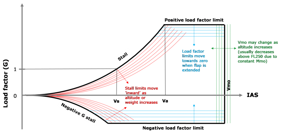
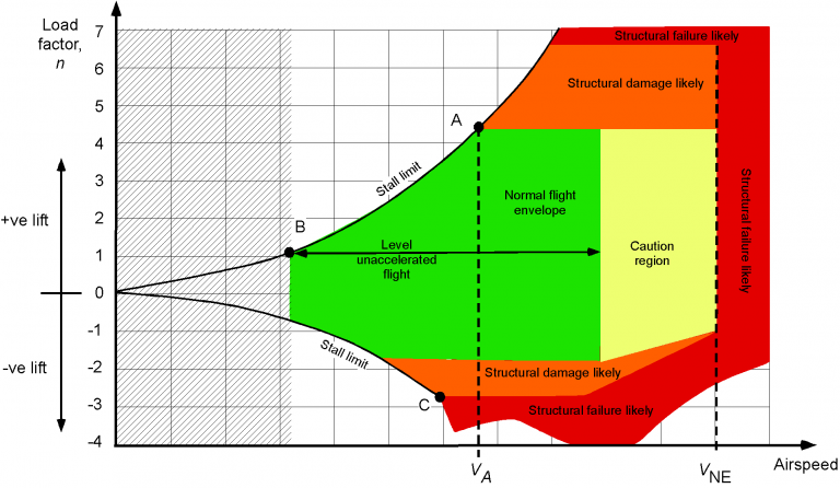
The V–n diagram—also called the flight envelope or load factor diagram—is one of the most important tools in flight mechanics. It graphically represents the relationship between an aircraft’s airspeed (V) and load factor (n), helping pilots and engineers understand the aircraft’s structural limits, maneuvering capabilities, and safety margins.
1. Introduction to Load Factor
Load factor latex[/latex] is the ratio of the aerodynamic lift generated by the aircraft to its weight:
![]()
- In straight, level, unaccelerated flight,
 .
. - In a pull-up maneuver or steep banked turn,
 .
. - In a push-over (nose-down maneuver),
 (can be negative).
Load factor describes the “g-forces” experienced by the aircraft and occupants. High load factors increase structural stress and can lead to pilot discomfort or blackout.
2. Purpose of the V–n Diagram
The V–n diagram defines:
- Structural limits: The maximum load factors the aircraft can sustain without permanent deformation or failure.
- Aerodynamic limits: The stall boundaries beyond which the wing can’t generate enough lift.
- Operational limits: Speeds at which full control deflection is safe or dangerous.
It effectively maps out the safe operational envelope for the aircraft.
3. Basic Axes and Shape
- Horizontal Axis (V): Airspeed (usually equivalent airspeed, EAS).
- Vertical Axis (n): Load factor.
The diagram typically has:
- Curved lines sloping outward from low speeds (stall boundaries).
- Horizontal lines marking structural load limits.
- Vertical lines marking maximum operating speeds.
The enclosed region is the area of safe flight.

4. Stall Boundaries
At low speeds, the maximum load factor is limited by stall:
- Positive stall line: Upper boundary.
![]()
Solving for speed at a given load factor:
![]()
As load factor increases, stall speed increases—this is called accelerated stall. The positive stall line slopes upward on the diagram.
- Negative stall line: Lower boundary, determined by negative lift coefficient limits.
Aircraft can’t fly above (or below) these lines because the wing stalls.
5. Limit Load Factor
The limit load factor is the maximum design load factor the structure can sustain without permanent deformation.
Typical values:
- Transport category aircraft: +2.5 to –1.0
- Utility category: +4.4 to –1.76
- Acrobatic category: +6.0 to –3.0
On the diagram, these are shown as horizontal lines at +n_limit and –n_limit.
6. Ultimate Load Factor
Structures must also withstand the ultimate load factor, usually 1.5 times the limit load factor. Exceeding ultimate load can cause structural failure.
- The limit defines operational restrictions.
- The ultimate defines catastrophic failure.
The diagram itself usually just marks the limit lines; the ultimate factor is a design criterion but not an operational boundary.
7. Maneuvering Speed (Va)
Maneuvering speed (Va) is a critical speed:
- Below Va: The aircraft will stall before it exceeds the limit load factor with full control input.
- Above Va: Abrupt or full deflection can exceed limit load factor without stalling first, risking structural damage.
Va is calculated by:
![]()
Va is shown on the diagram as the intersection of the positive stall line with the +n_limit line.
8. Maximum Operating Speed (Vmo/Vne)
- Vmo (Maximum operating speed) or Vne (Never-exceed speed) are vertical lines on the diagram.
- Beyond these speeds, control surfaces and structure may fail even at low load factors.
- Structural flutter, control reversal, and high dynamic pressure loads become risks.
These vertical lines define the right edge of the envelope.
9. Gust Envelope
Aircraft must also withstand gusts that instantly change the load factor.
A vertical gust introduces an instantaneous change in angle of attack, producing an incremental load factor:
![]()
Where:
 = Gust velocity
Gust lines expand the envelope upward (and downward) to show maximum expected loads due to turbulence. Regulatory standards (like FAR Part 25) define design gust velocities at different speeds.

10. Interpretation of the Diagram
The enclosed area in the V–n diagram is the safe operational envelope:
- Inside the envelope: Aircraft can maneuver safely without stalling or exceeding structural limits.
- Beyond stall lines: Wing stalls → loss of lift → departure from controlled flight.
- Beyond limit lines: Risk of permanent structural deformation.
- Beyond ultimate lines: Structural failure likely.
- Beyond speed limits: Flutter or failure risk even at 1g.
11. Load Factor in Turns
One common way to exceed load factor is in level turns. For a coordinated turn:
![]()
As bank angle ![]() increases, so does load factor:
increases, so does load factor:
- 30° bank: n ≈ 1.15
- 45° bank: n ≈ 1.41
- 60° bank: n = 2.0
At high bank angles, the aircraft may exceed its limit load factor or stall at higher speeds.
12. Summary of Key Points
- V–n diagram maps airspeed vs. load factor.
- Positive and negative stall lines define aerodynamic limits.
- Horizontal limit load lines define structural design limits.
- Va (maneuvering speed): Below which full control inputs won’t exceed limit loads (aircraft stalls first).
- Vmo/Vne: Never exceed speeds defining operational limit.
- Gust lines: Account for unexpected load factor increases from turbulence.
By consulting the V–n diagram, pilots can understand how fast and how aggressively they can maneuver without risking structural damage or aerodynamic stall. Engineers use the diagram to design safe, efficient aircraft structures that meet certification requirements.

