Understanding an airplane’s configuration and its major parts is essential in flight mechanics. Aircraft are designed to achieve a balance between aerodynamic efficiency, stability, control, structural strength, and mission requirements.
1. Airplane Configuration Types
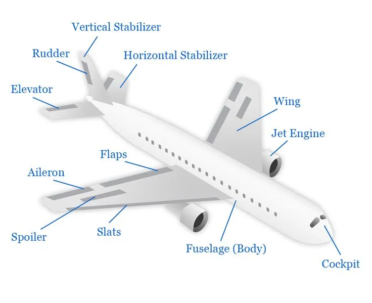
Airplane configuration refers to the overall arrangement of its major components.
1.1 Conventional Configuration
- The most common arrangement.
- Features a main wing, tail (horizontal and vertical stabilizers), fuselage, and engines (mounted on wings or fuselage).
- The horizontal tail provides longitudinal stability.
1.2 Canard Configuration
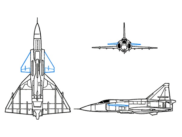
- Small forewing (canard) located ahead of the main wing.
- Canards provide lift and pitch control.
- Reduces the need for a large tail and can improve aerodynamic efficiency.
1.3 Tailless and Flying Wing
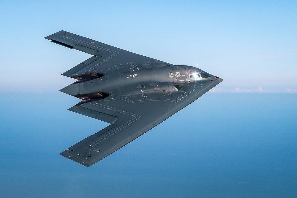
- No distinct tail surfaces.
- Control surfaces integrated into the wing itself.
- Examples: Northrop B-2 Spirit (flying wing design).
1.4 Tandem Wing
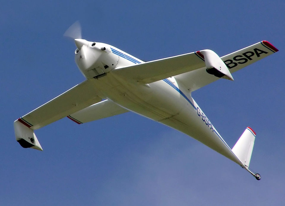
- Two main wings arranged one behind the other.
- Both wings provide lift.
- Less common but used in some light aircraft and UAV designs.
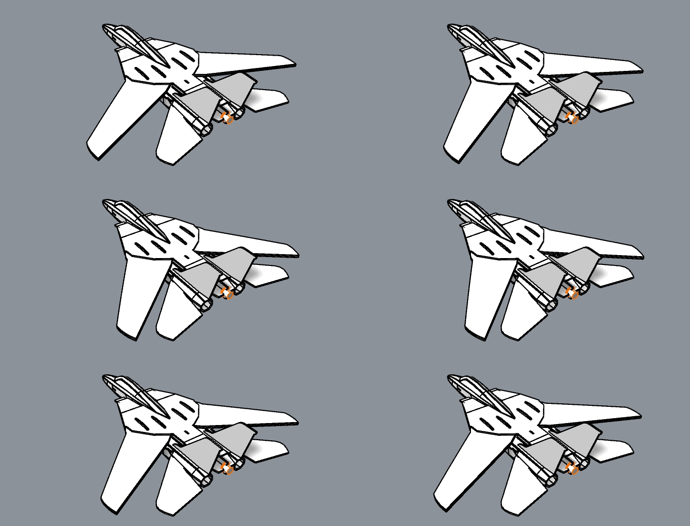
1.5 Variable Geometry
- Wings that change sweep angle in flight.
- Optimizes performance for different speeds.
- Example: F-14 Tomcat.
2. Major Parts of an Airplane
An airplane consists of several primary structural and functional components, each with a specific purpose.
2.1 Fuselage
- The central body of the aircraft.
- Houses crew, passengers, cargo, avionics, and fuel in some designs.
- Structural backbone connecting the wings and empennage.
2.2 Wing
- Primary lift-producing surfaces.
- May have high-wing or low-wing configurations.
- Equipped with control surfaces like ailerons and flaps.
- Airfoil shape generates lift via pressure differences.
![]()
Where:
 = Lift force
 = Air density
 = Airspeed
 = Wing area
 = Coefficient of lift
2.3 Empennage (Tail Assembly)
- Provides stability and control.
- Consists of:
- Horizontal Stabilizer: Controls pitch.
- Elevator: Movable surface for pitch control.
- Vertical Stabilizer: Controls yaw.
- Rudder: Movable surface for yaw control.
2.4 Landing Gear
- Supports the aircraft on the ground.
- May be fixed or retractable.
- Configurations: tricycle gear (nose wheel) or tail-dragger.
- Absorbs landing impact and enables ground movement.
2.5 Powerplant
- Provides thrust for flight.
- Types include:
- Piston engines with propellers.
- Turbojet, turbofan, turboprop, turboshaft engines.
- Location varies: nose-mounted, wing-mounted, tail-mounted.
2.6 Control Surfaces
- Essential for maneuvering:
- Ailerons: Roll control (differential deflection on wings).
- Elevators: Pitch control (on horizontal stabilizer).
- Rudder: Yaw control (on vertical stabilizer).
- Flaps: Increase lift at low speeds.
- Slats: Delay stall at high angles of attack.
- Spoilers: Reduce lift and increase drag.
2.7 High-Lift Devices
- Improve takeoff and landing performance.
- Include flaps, slats, Krueger flaps, and leading-edge extensions.
- Modify wing camber and area.
3. Secondary Components and Systems
3.1 Avionics
- Navigation, communication, autopilot, flight management systems.
3.2 Fuel System
- Stores and delivers fuel to engines.
- Includes tanks, pumps, and lines.
3.3 Electrical System
- Powers avionics, lighting, actuators.
3.4 Environmental Control
- Pressurization, air conditioning, de-icing.
4. Summary
Airplane configuration and parts are designed to meet performance, safety, and mission requirements. A well-balanced design ensures stability, controllability, structural integrity, and efficiency in flight.

